 avamaity
 Roeper Example
Here is an example from the book Short-circuit Currents in Three-phase Systems by Richard Roeper. I was surprised to find that my calculations using the admittance matrix method rendered with python did not tally with some of the results given in the book.
The example is the one towards the end of the book titled Example 3: Initial A.C. Short-circuit Currents I"k for the Five Kinds of Short Circuit in a Meshed System with Several Infeeds. What stumped me was that the three pole short impedance tallied to two decimal places yet the zero sequence impedance was close but not equal.
Since nothing would make sense without a circuit diagram, here is the interconnected system depicted in the book.
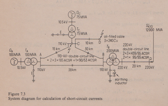
The fault point is at D. After detailing the equipment ratings and mesh connections, the book goes on to give a step by step account of the circuit reduction procedure. The impedance values for the positive-, negative-, and zero-sequence systems given in book are:
Z1D = Z2D = (1.776 + j9.232)Ω = 9.401Ω(φ=79.1o)
Z0D = (6.406 + j10.978)Ω = 12.710Ω(φ=69.73o)
Note that the cartesian and polar representations do not tally.
Here is a small script that calculates the above impedances using the admittance matrix method. The script starts of with the impedance calculations of each branch attached to a bus.
                    import numpy as np


                     #Constants

                     a = np.exp(2*np.pi/3.)

                     A = np.matrix( ((1., 1., 1.), (1., a**2., a), (1., a, a**2.)), dtype=np.complex64)


                     #System description at Bus A

                     S_NG1 = 100. #generator rated apparent power in MVA

                     U_NG1 = 10.5 #generator rated voltage in kV

                     xst_dG1 = 10.5 #relative initial subtransient reactance in percent

                     r_G1 = 0.3 #generator resistance in percent

                     S_NT1 = 100. # transformer rated capacity in MVA

                     U_NT1LV = 10.5 #in kV

                     U_NT1HV = 115. #in kV

                     u_kNT1 = 11.5 #in percent

                     u_RNT1 = 0.5 #in percent

                     n_ZT1 = 0.8 #ratio of zero to positive sequence impedance

                     #Sequence impedance calculations -----------------------

                     Z1_G1 = complex(r_G1, xst_dG1)*(1./100.)*((U_NG1**2)/S_NG1)*(U_NT1HV/U_NT1LV)**2

                     print 'Z1_G1 =', Z1_G1

                     Z2_G1 = Z1_G1

                     Z1_T1 = complex(u_RNT1/100., u_kNT1/100.)*((U_NT1HV**2)/S_NT1)

                     print 'Z1_T1 =', Z1_T1

                     Z2_T1 = Z1_T1

                     Z0_T1 = n_ZT1*Z1_T1

                     print 'Z0_T1 =', Z0_T1
Similarly the impedance calculations for devices (other than lines) connected to buses B, C and Q are as follows:
                    #System description at Bus B

                    S_NT2 = 200. # transformer rated capacity in MVA

                    U_NT2LV = 115. #transformer LV side nominal voltage in kV

                    U_NT2HV = 230. #in kV

                    u_kNT2 = 12. #in percent

                    u_RNT2 = 0.3 #in percent

                    n_ZT2 = 2.4 #ratio of zero to positive sequence impedance

                    #Sequence impedance calculations ------------------

                    Z1_T2 = complex(u_RNT2/100., u_kNT2/100.)*((U_NT2LV**2)/S_NT2)

                    print 'Z1_T2 =', Z1_T2

                    Z2_T2 = Z1_T2

                    Z0_T2 = n_ZT2*Z1_T2

                    print 'Z0_T2 =', Z0_T2


                    #System description at Bus C

                    S_NG3 = 75. #generator rated apparent power in MVA

                    U_NG3 = 10.5 #generator rated voltage in kV

                    xst_dG3 = 11.2 #relative initial subtransient reactance in percent

                    r_G3 = 0.3 #generator resistance in percent

                    S_NT3 = 75. # transformer rated capacity in MVA

                    U_NT3LV = 10.5 #in kV

                    U_NT3HV = 115. #in kV

                    u_kNT3 = 10. #in percent

                    u_RNT3 = 0.6 #in percent

                    n_ZT3 = 0.8

                    #Sequence impedance calculations ------------------

                    Z1_G3 = complex(r_G3, xst_dG3)*(1./100.)*((U_NG3**2)/S_NG3)*(U_NT3HV/U_NT3LV)**2.

                    print 'Z1_G3 =', Z1_G3

                    Z2_G3 = Z1_G3

                    Z1_T3 = complex(u_RNT3/100, u_kNT3/100.)*((U_NT3HV**2)/S_NT3)

                    print 'Z1_T3 =', Z1_T3

                    Z2_T3 = Z1_T3

                    Z0_T3 = n_ZT3*Z1_T3

                    print 'Z0_T3 =', Z0_T3


                    #System description at Bus Q

                    Sst_kQ = 12000. #initial a.c. short circuit power at 2Q in MVA

                    U_NQ = 230. #rated voltage of the system at point of connection 2Q in kV

                    U_Q = 220.

                    U_N2 = 115.

                    RX_Q = 0.1

                    #Sequence impedance calculations ------------------

                    Z1Q = complex(0.1, 1.0)*1.1*((U_Q**2)/Sst_kQ)*(U_N2/U_NQ)**2

                    print 'Z1Q =', Z1Q

                    Z2Q = Z1Q
Next the interconnecting branch impedances are calculated.
                    #Bus interconnections

                    Z1_12 = (3.154+7.657j) #in ohms

                    Z2_12 = Z1_12 #in ohms

                    Z0_12 = (10.431+31.673j) #in ohms

                    Y0_12 = complex(0, 38*314*(5.4-1.43)*(10.**-9)) #in mhos

                    print 'Y0_12 =', Y0_12

                    Z1_23 = (2.490+6.045j) #in ohms

                    Z2_23 = Z1_23 #in ohms

                    Z0_23 = (8.235+25.005j) #in ohms

                    Y0_23 = complex(0, 30*314*(5.4-1.43)*(10.**-9)) #in mhos


                    Z1_13 = (1.245+3.023j) #in ohms

                    Z2_13 = Z1_13 #in ohms

                    Z0_13 = (4.118+12.503j) #in ohms

                    Y0_13 = complex(0, 15*314*(5.4-1.43)*(10.**-9)) #in mhos


                    Z1_2Q = (0.173+0.980j) #in ohms

                    Z2_2Q = Z1_2Q


                    Z1_34 = (0.840+1.260j) #in ohms

                    Z2_34 = Z1_34

                    Z0_34 = (5.440+3.430j)

                    Y0_34 = complex(0, 1/(2*1.098*(10.**3))) #in mhos
We can now form the adimttance matrix like so:
                    #Creation of Y matrix for positive and negative sequence components

                    y1_11 = 1/(Z1_G1+Z1_T1)+(1/Z1_12)+(1/Z1_13);

                    y1_12 = -1/Z1_12;

                    y1_13 = -1/Z1_13;

                    y1_14 = 0+0j;

                    y1_21 = y1_12;

                    y1_22 = 1/(Z1_T2+Z1_2Q+Z1Q)+(1/Z1_12)+(1/Z1_23);

                    y1_23 = -1/Z1_23;

                    y1_24 = 0+0j;

                    y1_31 = y1_13;

                    y1_32 = y1_23;

                    y1_33 = 1/(Z1_G3+Z1_T3)+(1/Z1_13)+(1/Z1_23)+(1/Z1_34);

                    y1_34 = -1/Z1_34;

                    y1_41 = 0+0j;

                    y1_42 = 0+0j;

                    y1_43 = y1_34;

                    y1_44 = 1/Z1_34;


                    Y1 = np.matrix( ((y1_11, y1_12, y1_13, y1_14),

                                      (y1_21, y1_22, y1_23, y1_24),

                                      (y1_31, y1_32, y1_33, y1_34),

                                      (y1_41, y1_42, y1_43, y1_44)) )


                    #Creation of Y matrix for zero sequence components

                    y0_11 = (1/Z0_T1)+(1/Z0_12)+(Y0_12/2.)+(1/Z0_13)+(Y0_13/2.)

                    y0_12 = -1/Z0_12;

                    y0_13 = -1/Z0_13;

                    y0_14 = 0;

                    y0_21 = y0_12;

                    y0_22 = 1/(Z0_T2)+(1/Z0_12)+(Y0_12/2.)+(1/Z0_23)+(Y0_23/2.);

                    y0_23 = -1/Z0_23;

                    y0_24 = 0;

                    y0_31 = y0_13;

                    y0_32 = y0_23;

                    y0_33 = 1/(Z0_T3)+(1/Z0_13)+(Y0_13/2.)+(1/Z0_23)+(Y0_23/2.)+(1/Z0_34)+(Y0_34);

                    y0_34 = -1/Z0_34;

                    y0_41 = 0;

                    y0_42 = 0;

                    y0_43 = y0_34;

                    y0_44 = (1/Z0_34)+(Y0_34);


                    Y0 = np.matrix( ((y0_11, y0_12, y0_13, y0_14),

                                      (y0_21, y0_22, y0_23, y0_24),

                                      (y0_31, y0_32, y0_33, y0_34),

                                      (y0_41, y0_42, y0_43, y0_44)) )
Simple matrix inversion gives the required positve, negative and zero sequence impedances.
                    Z1 = Y1.I

                    print 'Z1_D =', Z1[3,3]

                    print 'Z1_D (magnitude) =', abs(Z1[3,3])

                    print 'Z1_D (phi) =', np.angle(Z1[3,3], deg=True)


                    Z0 = Y0.I

                    print 'Z0_D =', Z0[3,3]

                    print 'Z0_D (magnitude) =', abs(Z0[3,3])

                    print 'Z0_D (phi) =', np.angle(Z0[3,3], deg=True)

                    The results are:


                    Z1_D = (1.77625416846+9.23176366127j)

                    Z1_D (magnitude) = 9.40109244548

                    Z1_D (phi) = 79.1089967228

                    Z0_D = (6.41623849995+10.9769540055j)

                    Z0_D (magnitude) = 12.7146229094

                    Z0_D (phi) = 59.6929014604
What could be the reason for the difference in Z0 values?